
Design guidelines for bent sheet metal parts.
Here you'll find important specifications on bend radii, cut-outs, bend lengths and flanges for designing bent sheet metal parts.
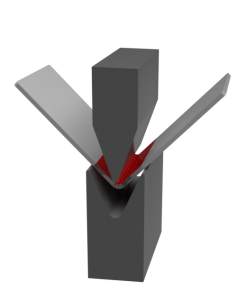
1. Inner bend radius = sheet thickness
The inner radius of a bend should be designed equal to the sheet thickness.
With the air-bending method we use, however, the effective manufacturing radius only corresponds to this value approximately and only for a 90° bend. For larger opening angles the radius becomes larger, for smaller opening angles smaller. For questions about special bend radii, please contact our Helpdesk.
2. Cut-outs in the bend zone
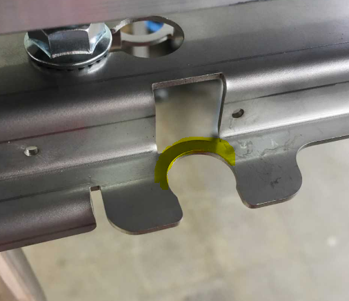
If cut-outs are located in the bend zone, they can deform during bending. Edges that do not run perpendicular to the bend can also show deformations after the bending process. The deformations are more pronounced with thick materials and longer cut-outs along the bend line than with small holes or short cut-outs in thin material.
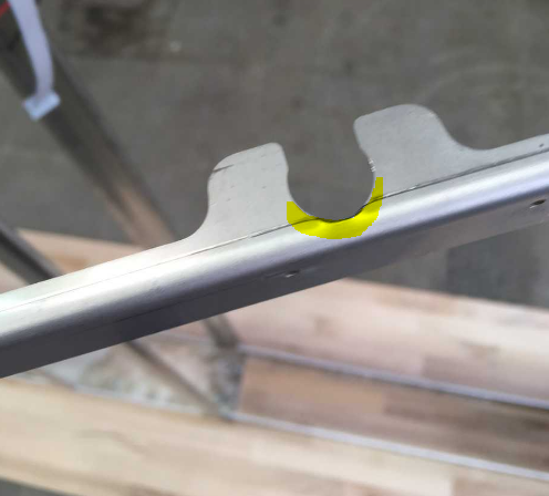
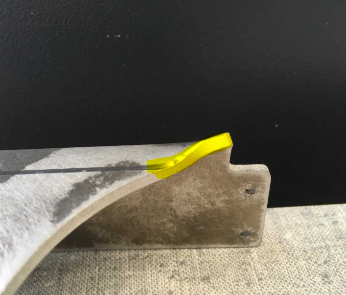
Blexon automatically detects cut-outs with deformation risk in the bend zone and displays a warning. You can open the item in the CAD viewer and show the bend zone. This way you immediately see which cut-outs lie within the bend zone.

Blexon checks the bend zone automatically. Cut-outs with deformation risk can be automatically relieved if needed.
If possible, the cut-outs should be moved and removed from the bend zone. You can measure the bend zone directly in the model and thus determine how far the cut-outs need to be moved. To do so, click on the end of the bend zone and, for example, on the face. This gives you the extent of the bend zone and lets you move the cut-out precisely.
If you cannot move the cut-outs, you can in the CAD viewer have a relief cut created automatically with one click. Then carefully check the adjusted CAD model. Since the automatically inserted relief cut changes the geometry of the part, a review of the adjustment is required.

3. Missing or too small corner reliefs
When two flanges meet in a corner, a corner relief is needed so that the sheet metal part can be manufactured without defects. Corner reliefs can have a wide variety of shapes. The simplest form is a rectangular cut-out. Many CADs provide a multitude of different reliefs. If no corner reliefs or reliefs that are too small have been designed in a corner, the sheet metal part cannot be manufactured and an error appears on the portal.

To design a sheet metal part with a bend, be sure to use a CAD intended for sheet metal design (CAD with a sheet metal module). In such a CAD, corner reliefs can be placed very easily or are set automatically. If you do not have such a CAD, we recommend Fusion 360 by Autodesk. You'll find a quick guide for Fusion 360 here.
4. Minimum flange length
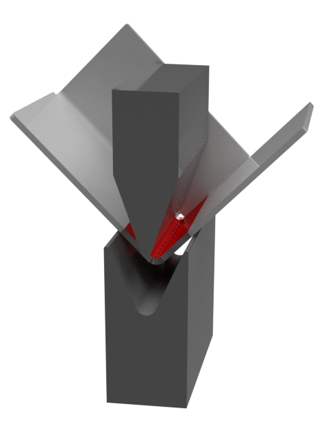
If the flange length is too short, one side of your sheet metal part does not rest correctly on the bending tool, so that manufacturing is not possible. In this case, an error message appears on the portal. You can measure and adjust the flange length directly in Blexon's in-browser CAD. This video shows you how it works.

| Sheet thickness (s) | x for angle greater than 90° (w) | x for angle less than 90° (w) |
|---|---|---|
| 0.5 mm | 4.5 mm | 7.5 mm |
| 0.8 mm | 4.2 mm | 9.2 mm |
| 1 mm | 4.5 mm | 9 mm |
| 1.5 mm | 7.5 mm | 9 mm |
| 2 mm | 7.5 mm | 11 mm |
| 2.5 mm | 9.5 mm | 13 mm |
| 3 mm | 12.5 mm | 19 mm |
| 4 mm | 18.5 mm | 23 mm |
| 5 mm | 25 mm | 33 mm |
| 6 mm | 32 mm | 37 mm |
| 8 mm | 35 mm | 49 mm |
| 10 mm | 47 mm | 62 mm |
| 12 mm | 60 mm | |
| 15 mm | 89 mm |
5. Maximum box height
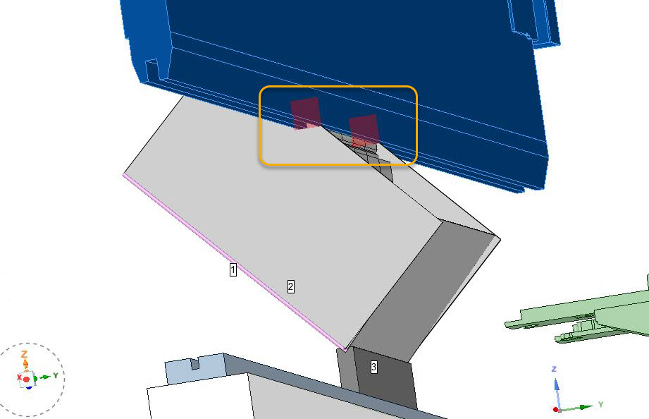
As soon as a sheet metal part has several bent sides crossing each other, a collision with the bending machine or the bending tools occurs above a certain flap height. At Blexon you can order such parts (boxes / cases) up to a height of 260 mm.
6. A hem is only possible up to 2 mm sheet thickness
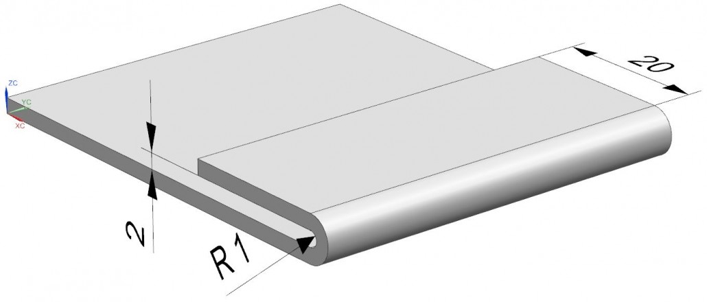
Hems are only possible for sheet thicknesses up to 2 mm. Also make sure that the hem has an inner radius and is not pressed completely flat.
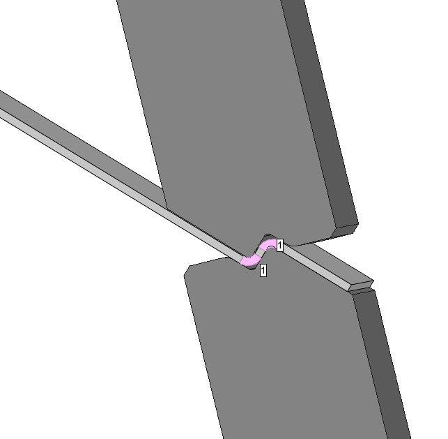
7. Z-bend with standard tools
For two successive bends (Z-bend), the following minimum dimensions are achieved with standard tools.

| Sheet thickness (s) | x for angle greater than 90° (w) | x for angle less than 90° (w) |
|---|---|---|
| 0.5 mm | 4.5 mm | 7.5 mm |
| 0.8 mm | 4.2 mm | 9.2 mm |
| 1 mm | 4.5 mm | 9 mm |
| 1.5 mm | 7.5 mm | 9 mm |
| 2 mm | 7.5 mm | 11 mm |
| 2.5 mm | 9.5 mm | 13 mm |
| 3 mm | 12.5 mm | 19 mm |
| 4 mm | 18.5 mm | 23 mm |
| 5 mm | 25 mm | 33 mm |
| 6 mm | 32 mm | 37 mm |
| 8 mm | 35 mm | 49 mm |
| 10 mm | 56 mm | 62 mm |
| 12 mm | 60 mm | |
| 15 mm | 89 mm |
8. Z-bends with offset tools
Z-bends can be produced on thin sheets (aluminium up to 2 mm, steel and stainless steel up to 1.5 mm) with special offset tools. With these offset tools, smaller offset heights (4/6/8 and 10 mm) are possible. Depending on the region, not all offset heights are available. For questions, please contact our Helpdesk.