

Design guidelines for countersinks in sheet metal parts.
Here you'll find important specifications for designing and defining countersinks in sheet metal parts.
1. Countersunk screws
The only prerequisite for automatic detection of formed standard countersinks are suitable diameters for the countersink head (countersink diameter) and the screw passage (through-hole diameter).

Example
A countersink A M3 in 2 mm aluminium is defined there as follows, for example:
A M3 (6,7 mm/4,1 mm/90°)
These values mean that the countersink diameter must be 6.7 mm and the through-hole diameter 4.1 mm. Blexon automatically detects such standard countersinks and you can accept them with a mouse click on the checkmark.
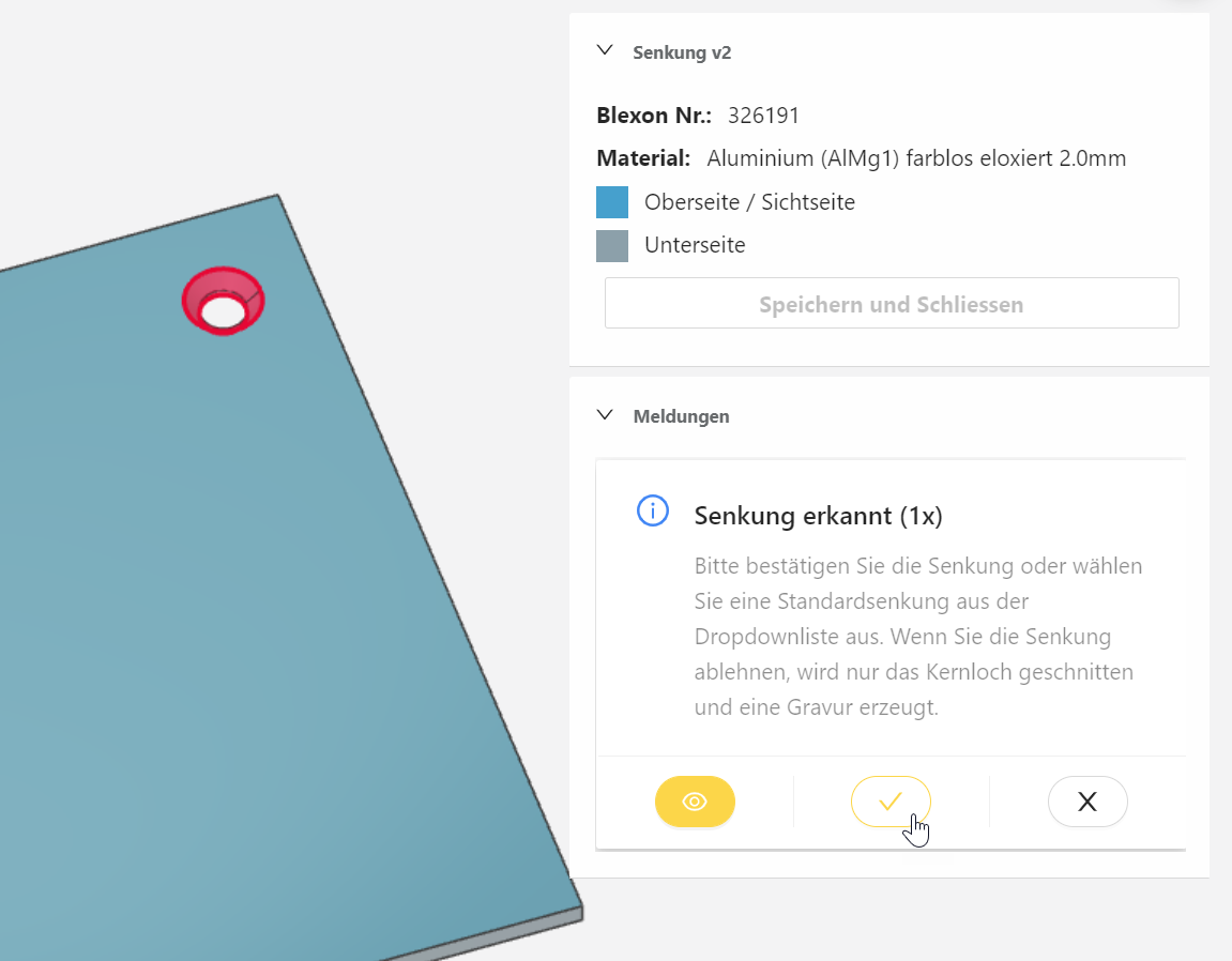
The possible size of the countersinks depends on the material thickness. You'll find the details in the following table.
2. Cheese-head screws
Countersinks for cheese-head screws are defined by the two diameters (top and bottom) and the depth of the countersink.

The possible size of the cylindrical counterbores depends on the material thickness. You'll find the relevant details in the table below.
3. Non-standard countersinks
If the countersink diameter and the through-hole diameter do not match a standard size, Blexon still detects the countersink. You then have the option of defining the countersink in Blexon's in-browser CAD and having it produced as well.

4. Reject a detected countersink
If Blexon detects a countersink but none of the standard countersinks meets your requirements, you can reject the countersink. To do so, click the eye in the message and then the cross. Blexon then changes the CAD model so that only the through-hole is cut according to the design. The countersink size is engraved. This lets you easily produce the countersink yourself.
5. Manually assigning a countersink to a hole
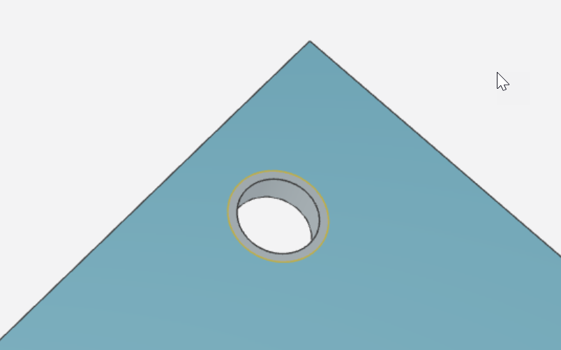
Did you forget the countersink or cylindrical counterbore in your CAD model? No problem, you can assign a countersink to any hole directly in the sheet metal portal.

